Friday, September 25, 2015

Passenger Geep No. 8551

One of my favorite locomotives is PRR GP-7 no. 8551. The 8551 along with its sister locomotive 8552 were two of only three hood units that the Pennsy ever ordered with roof top air tanks. These two units were assigned to Williamsport to protect passenger train service on the Washington-Buffalo trains, but most of the time they could be found hauling local freight trains.  As a result, they spent a lot of time on the Elmira Branch. 

In the mid-1950's they provided power for the skeletal remains of the Williamsport-Canandaigua passenger service hauling the last remnant of that service in the Commonwealth of Pennsylvania.  By 1956 all passenger service was eliminated on the Branch.  In the era that I model (Fall of 1956) all passenger service was gone and 8551 hauled only freight.  [Though I plan to use some modeler's license and run some form of passenger service.]

The above photo shows the 8551 on the fill slope approaching the Seeley Creek Bridge and Kendall Tower can be seen just to the right of the scene. No commercially produced GP-7 currently exists in S scale. So if you're trying to model a GP-7 you can try to find one of the brass versions imported by Sunset Ltd. many years ago (with really bad running mechanisms), or convert one from an American Models (AM) GP-9.  I chose to do the later.

The AM GP-9s are fairly good running locomotives with a proven drive system. Several years ago Des Plaines Hobbies (DPH) started producing an exquisitely detailed GP-7 long hood, which really facilitated the conversion. But rather than describe the conversion process here, it's better to refer you to the article on the conversion that I wrote for the S Scale Special Interest Group.  You can find the article here:


I did the locomotive conversion about three years ago, and like many things I do (admittedly), its was about 95% complete. I installed DCC and it was running around the layout, but it still needed lights, window glazing, numbers in the number boards, marker lights and a crew. The glazing and the crew were not an issue, but the number boards were.  It seems that the decal set didn't include enough of the numeral "5" to letter all of the number boards. With four number boards, I needed eight 5's and the decal set only included two!  There was no way hat I wanted to purchase 4 decal sets to letter one locomotive.  So I had to consider another alternative.

I scanned the numerals from the set and created the 8551 number board in Photoshop.  When I was satisfied with the scale of the number board, I printed a bunch of them on glossy photo paper as shown below:


Next I trimmed the number boards and outlined the edge of the photo paper with a black Sharpie so that no white was showing. The DPH shell is recessed in the area of the number boards so the thickness of the photo paper fills the recess nicely.

The lights were a bit of a challenge as well.  Neither AM or DPH makes an clear plastic insert for the twin sealed beam headlights.  I really wanted to have individual bulbs anyway and they had to be LEDs if I were to insert them into the headlight openings.  Bulbs would generate too much heat and potentially melt the superbly detailed casting.  Recently, I found some small diameter clear incandescent looking LEDs that could slip into the twin headlight openings and they are called "tower LEDs" by Minitronics.   The LEDs have a small (2mm) cylindrical projection, or tower, that can fit inside the headlight housing.  It's possible to glue the two LEDs together, wire them in parallel, and mount them to the inside of the long and short hoods.  With the decoder that I used, each LED needed a voltage limiting resistor, but even with that the twin LEDs are really bright!  It will be neat to watch this unit cast its headlight beams around the layout with the room lights off.


I now consider this project complete, though if I wanted to be completely accurate, I would install windshield wipers and sunshades above the cab windows.  I may do that some day but right now 8551 has some cars to pull.

Thursday, September 24, 2015

Layout Room Access

I've reached the part of layout construction where the bench work meets the access to the room.  I've been going back and forth in my mind for some time now over the various options of how folks will get into the layout room at the point where the alignment crosses the door opening.  I had one hard and fast rule - NO DUCK UNDERS!  I'm not getting any younger and neither are my guests so that option was ruled out quickly.  Beyond that there are a multitude of options and I needed to choose one that best suited me.

My first obstacle was the fact that the track alignment is on a curve at this location, and there was no way around that.  Plus I wanted to have some scenery on each side of the track so that it blends in well with the adjacent segments of the layout.  The first option that I considered was a roll in/out section.  It would resemble a rolling cart and would slide in and out and roll out of the way when access to the room is needed.  This option would enable me to fully scenic the top of the cart and when in place it would look like it was part of the layout.  This idea really appealed to me but the drawback is that it would be supported on casters rolling on an uneven concrete floor and alignment at track level could be challenging.  Besides, someday I may want to install carpeting and further adjustments would be necessary.

I then considered a swinging gate.  These have become quite popular and I really gave it a lot of consideration, but the curved track alignment was what convinced me to look at other alternatives.  Next, I considered a lift out section, but with a 26-in. span the section would be quite heavy and I wasn't sure where the section would go when it wasn't in place.  Most likely it would just stay there and it would by default become a duck under.

So that left the classic hinged drawbridge.  I first considered a bridge that would lift up, but that would require something to hold it in place when it's in the upright position.  In addition it would need some counterweights or locking mechanism so that it didn't swing down with all its weight and possibly hit someone.  I ended up with a hinged drop leaf section:

The bridge section is hinged and drops down to clear the opening.  It's constructed from 3/4" cabinet grade plywood and secured to two sections of 2x2's underneath to give it plenty of rigidity.  When hanging down all of the weight is supported by the hinges and when its raised two sliding dead bolts lock it in place and provide sufficient indexing to keep the rails in alignment.  A curved facia helps the section look less like a bridge and more like a piece of the layout.

Here's a photo of it in the raised position:

The photo shows the sliding dead bolt that holds the bridge section in place.  This is the second set of dead bolts that I installed.  The first set was a cheaper version called a barrel bolt.  It seemed that the barrel bolt housing had a lot of slop to it and didn't provide enough indexing to keep the rails in alignment.  I quickly removed them and installed two of the dead bolts shown in the photo on each side of the bridge and when locked in place, the bridge is very secure.

This photo shows the gap at track level:

I secured the track to the roadbed and then cut the gaps in the rails.  Next I'll remove the ties on each side of the gap and install PC ties with the rails soldered to them for a little better protection at the ends.

There's no power on the bridge section yet but I did back a train over the gap and alignment was very smooth.  I'm really please with how well this turned out.

Tuesday, August 4, 2015

Video a Train Crossing the New Seeley Creek Bridge

 
The attached video shows a short train crossing the the new bridge. From this perspective you can see Kendall Tower and Southport Yard beyond.

Thursday, July 30, 2015

The Alco PA

This is a first for me - two posts on the same day. Now that Seeley Creek is well in hand, I turned my focus back to rolling stock revisiting a project that I started years ago. If you go back to my February 2013 post, you can read about my exploits of trying to create the perfect Alco PA in S scale. Without rehashing my previous post, the short of it is that neither of the two commercially available versions of the PA are even close to accurately representing Alco's famous passenger locomotive. But if you combine the best features from both, a reasonable model can be created. 

This is a photo of the PA after the transformation. It's crude but a far cry better than either of the two as manufactured versions.  The model is attached to an Omnicon PA conversion mechanism (long out of production but available from time to time on Ebay.

After some consultation with my friend Bud Rindfleisch, and perusing literally hundreds of PA photographs from every conceivable angle (as well as one trip to Portland, OR to see the sole surviving PA), we concluded that the AP nose was too angular and needed to be rounded on the corners both vertically and horizontally on the top of the nose.  The other area that needed help was the front cab windows, as they were were too rectangular.  Photos revealed that the top of the windows were gently arched and the lower edge was curved downward.  All of this would require modification.  The American Models skirt between the trucks was also a big problem as it extended vertically down from the car body instead of curving inward. 

The big challenge was rounding the corners of the nose because it meant that a good amount of cast-on detail would have to be removed.  The number boards would have to be removed as well as the front anti-climber and buffer plate. Fortunately for PRR modelers the Pennsy replaced the as-built number boards with their own design angled number boards (though in my case that meant more scratch building).  The anti-climber and buffer plates were not quite right on the AF version anyway, so that meant an opportunity to correct another flaw.

This is a photo of the completed model nearly ready for the paint shop:

You can clearly see the difference with the rounded  corners and the new side skirt between the trucks. In this view you can also see the new Pennsy number boards and anti-climber/buffer plate. You can also make out the other Pennsy specific details such as the air intake grills added to the nose and the train phone antenna system. I added new fairing above and behind the cab side windows and above the front windows as per the prototype.  You may also notice that this is a non-dynamic brake version of the PA. I removed the DB's on the car body roof and replaced them with a smooth sheet of styrene. I have a few more details to fabricate before painting, such as the coupler cut levers above the front corner steps and grab irons above the front windows and other places.  I'm really pleased  with the way this turned out.  Here's a photo of a real PA (though not Pennsy) for comparison:


Seeley Creek Crossing Complete

My last post ended with painting the base for what would become Seeley Creek. Now it's time to add the glossy medium that will represent the water's surface. This view shows the first application the acrylic gloss media to the painted stream bed. The  media dries clear and the blue tint shown in the photo will disappear when the acrylic material is dry.  This is the first of several coats and I quickly learned not to introduce air bubbles into the media.  If that occurs on the first coat, it can be corrected on the second and any subsequent applications.  The acrylic  gloss media is best applied with a small round tipped paint brush.  I like using this stuff because it dries clear, has no odor, and clean up is simple with just soap and water.  When dry the surface texture is very glossy and has gentle ripples in it that nicely represents flowing water.  Since I model the Fall, most streams are in low flow conditions, so I didn't need to introduce any rapids or "white water" conditions.

The next step in the process was to extend the tree line down the hillside in the background and  blend it with the photos in the backdrop.  I began by painting a tree line on the backdrop along the ridge line of the hillside with dark brown paint.  It's not important that the painted area look like trees, because it will be covered by foliage.  It's there so that the light backdrop doesn't show through the understory of the forest.

I also used a foliage color palette that was consistent with the trees that were in the photo backdrop, and placed smaller trees in the back and larger ones in the front to create the effect of distance.

Here's a close-up of the trees showing a variety of foliage type.  The edge of the forest includes smaller bushes and vegetation to fill the gap between the ground cover and the tree canopies. (More on my tree making process in an upcoming post) The green florist foam that formed the base of the hillside made for easy planting of the trees. I use an awl to make a tiny hole, and then push the base of the tree into it. That's all there is to it. This view also shows the ground up leaves that form the base of the forest.  In retrospect, I probably only needed the ground up leaves in the foreground of the forest and not over the entire hillside.

This view shows the tree line extending down the hillside.  Note the smaller trees to the left and larger, closer trees to the right.  Also note how the brown painted ridge line disappeared, but allows no blue sky to project through the tress.

In this view the tree line extends all of the way to the water's edge and opens up just enough to show the field in the photo backdrop.  I added some static grass on the right which will extend under the right bridge abutment.  I still have more trees to plant on the hillside, but wanted to complete the area behind where there bridge will go as the rest of the scenery can placed once the bridge is set.

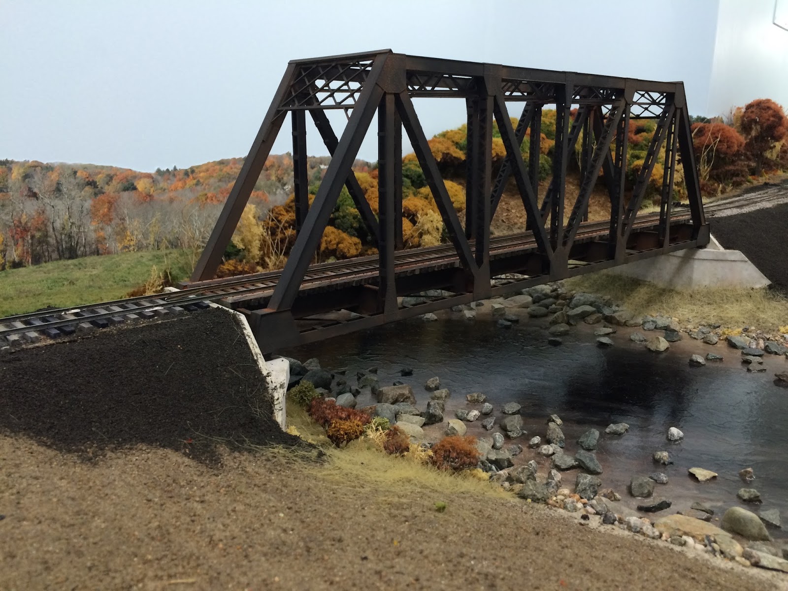
I then set the bridge on its abutments and shimmed the bridge bearings until the deck was level and at the proper elevation.  I connected the track to the adjacent ties but otherwise did not secure the bridge in case it ever had to be removed. The fill slopes on the approaches were covered with cinder like material and static grass was applied under the bridge.  Work on the foreground details has begun under the near abutment and much work is still needed to complete the scene, but for now the bridge is serviceable.

This is my favorite shot of the completed scene taken from under the bridge.  It appears as if the stream continues on, but in realty it ends a short distance away.


Thursday, July 9, 2015

Back to the Bridge

I've really been pushing myself to complete the truss bridge especially now that the stream bed and surrounding scenery is taking shape. Both trusses are now complete and attached to the bridge deck. I was pleased with how well the painting of the lattice work turned out.  I was concerned that the interior portion of the lattice beams would be the color of the white Evergreen styrene, but that wasn't the case at all.  I was able to angle the tip of my airbrush sufficiently to paint mostly all of the interior space.  A few hard to get places will need some touch up with a brush, but overall I was pleased.

With the trusses installed it has become quite an impressive structure and incredibly strong. I don't think there'll be an deflection to worry about and all of the joints appear to have bonded well.

It still has a bit more work especially on the upper sway bracing. Fortunately Plastruct makes a diagonally braced styrene joist that is the proper dimension for the sway bracing.  That being said, it'll still be a challenge because the they not only extend perpendicular to the panel points, but diagonally in an X pattern between them.

Nonetheless, I'm pleased with the progress and it looks rather different than it did a few months back.  Here's a photo from my September 11th blog post.  I never thought that it would ever progress this far considering all of the exhaustive scratch building.

Wednesday, July 8, 2015

Detailing Seeley Creek

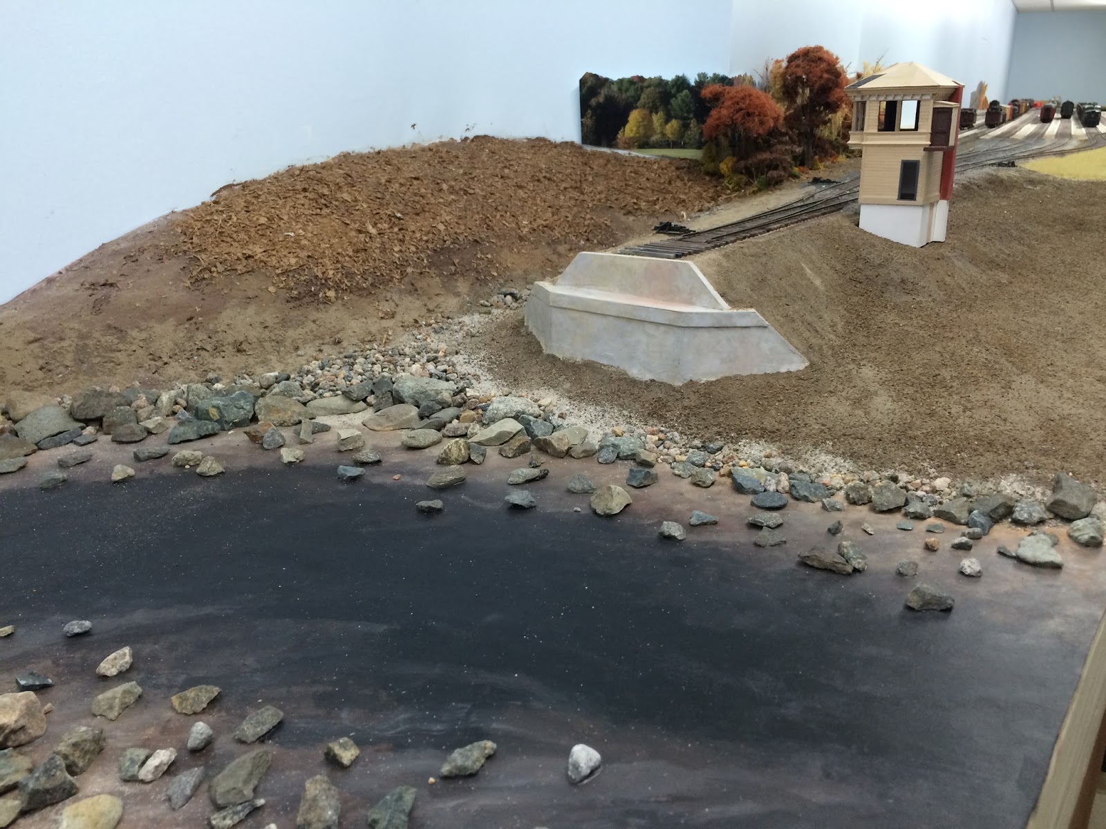
With the Seeley Creek bridge nearing completion, I now need to focus on completing the stream bed beneath were the structure will ultimately be placed.  The stream bed started out as a flat piece of Masonite and now it's time to make it look like flowing water.  The first step is to paint the bottom so that it will look like a stream.  For this I used acrylic paint and started with lighter shades of tan and gray near the shoreline and gradually added darker color until it became pure black near the center of the creek.  Ultimately, I'll simulate flowing water by coating the painted stream bed with acrylic gloss matte medium.  That's still a ways off as I have to line the banks with rocks and finish adding the ground texture on the adjoining slopes.

Here's a photo of the painted stream bed.  The lighter lines flowing into the dark area represent a bit of turbidity form water flowing around rocks and across the shallower parts of the stream.  Also in this view you can see both abutments of the truss bridge.  The abutments are made from mat board and 1/32" plywood covering the wood risers that are part of the original benchwork.

The stream bank needs more rocks...a lot more!  Much of the geology in this area is made up of glacial till.  Huge rocks that were moved thousands of years ago during the ice age and deposited  along stream beds or areas there were eventually  eroded by streams.

This photo shows the completed rock lined stream bed.  The rocks simply came from my backyard. I tried to select stones that were flat on one side and glued them randomly to the painted Masonite. I used smaller stones and fine beach sand behind the larger stones as a transition to the embankments on the bridge approaches. Once all the stones are secure, I'll brush on the gloss acrylic medium to represent the water.

I can't take credit for the process.  It goes way back to the early 1980's and Dave Frary's book - Easy to Build Model Railroad Scenery published by Kalmbach in 1982.  I've used this method on many occasions and the results are quite spectacular.  I personally prefer it to pouring resin to represent water, especially moving water.  We should be able to see the results in my next post.

One more shot of Seeley Creek looking back toward Southport yard. You can see Kendall tower sitting on it's foundation on the approach embankment to the bridge.  Next steps include extending the photo backdrop and planting lots of trees on the far hillside.