Thursday, September 11, 2014

Beyond Southport

At the south end of Southport Yard, the Elmira Branch mainline crossed Seeley Creek on a single  track, through-truss bridge.  All of the yard tracks converged at this point and the truss bridge was literally a few yards beyond the point of switch.  This was also the location of Kendall Tower which controlled movements through the yard.

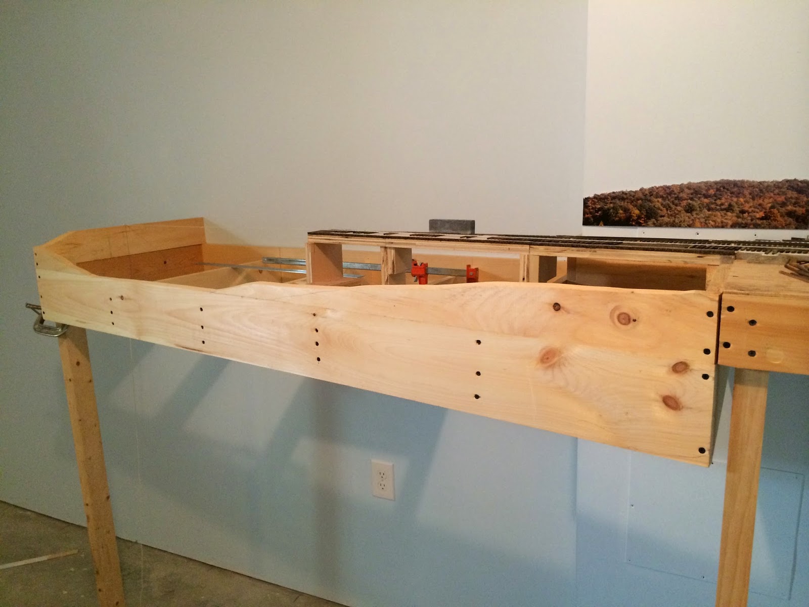
My next extension of the layout includes the Seeley Creek crossing.  This is where the layout construction gets interesting because until this point, the rest of the layout was flat table-top topography and now the grade needs to dip below track level to accommodate the stream.  For this effort, I used deeper sections of framing material cut to the profile of the descending stream bank.  Seeley Creek is not a particularly wide or deep stream, but because of flood potential in the Chemung River Valley the abutments were set widely apart, and required a clear span without a center pier.  The distance between abutments is 23-in. in S-scale in order to accommodate a 120-ft. span.

I began constructing the bridge some time ago (see my May 2012 post), and now the need is growing.  As I mentioned previously, there is a real void in S-scale when it comes to through-truss bridges, and scratch-building one has been a real challenge.  Finally after considerable time spend fabricating the individual truss elements, I now have the floor pieces and one of the two trusses assembled.

I needed to complete the floor system so that I could set the abutments both horizontally and vertically.  Next, I set the completed truss in position just to get the feel of how the finished structure would look on the layout.  I must admit that it was quite impressive and it will certainly be a focal point on the layout.

The bridge is a 6-panel Pratt Truss Bridge and while visually similar to the Pennsy's Seeley Creek Bridge, it's still a compromise. The prototype structure is a 7-panel truss and three of the bottom panel chords are pin connected.  As much as I wanted to make it a 7-panel truss, there was no way that the layout could accommodate it without sacrificing the curve radius that will occur just beyond the south end of the bridge.  I did not want any mainline tracks dipping below 48" and now it appears that I can hold at least 52" at this point.  As for a pin connected bridge, I did not want to attempt that in styrene.

Seeing the bridge come to life is now giving me incentive to complete the other truss.  Making the laced girders is the most time consuming and tedious part.  And as much as I would like to call this effort done, I'm probably going to build a stand in structure out of laminated plywood until the final bridge is ready.

Some folks have commented previously that I should have considered using black styrene instead of white because painting it black will be difficult.  Yes, that's true.  Painting all those nooks and crannies especially the interiors of the laced girders will be difficult.  But, unfortunately black styrene is readily available in sheets but dimensional pieces are hard to find.  There was no way that I wanted to, or could accurately cut the black sheets into the dimensional strips that I needed.  Maybe some day Evergreen will offer dimensional strips in black, but when this structure is complete, I won't be too anxious to build another.

As Trevor Marshall frequently says in his S-scale Port Rowen blog, "It's time to enjoy an adult beverage."

Thursday, June 26, 2014

Around the Corner

Now that the Southport Yard portion has been placed against the wall, benchwork has progressed to the corner of the room.  The corner will contain the Southport roundhouse and engine terminal, which is a good location for an engine facility.

The corner section includes a turntable pit which I installed before positioning the table into the corner of the room.  The pit diameter is 120-ft, which is more than 19-inches in S-scale.  I need a pit that large to accommodate an I-1 with a long tender.  Behind the turntable I plan to construct a 6-stall round house.  I do plan to add a curved section of backdrop to eliminate the square corner.

I was using Homasote as roadbed, principally under Southport yard with disappointing results.  I've had to rebuilt much of the track because the Homasote was uneven and the plywood underneath was too thin.  So, my latest benchwork practice uses thicker 3/4" plywood with cork roadbed. The corner section was built with Homasote over thin plywood.  It was cut from a single sheet of Homasote so unevenness wasn't a problem.  I added extra stiffeners under the plywood to prevent it from warping.  But, from here on out, I'm done with Homasote.

With the engine terminal in the corner, it allows me plenty of space for the mainline track to curve toward the front edge of the layout affording me a generous 60-in. radius curve.  At this location, two main tracks extend from the yard and will converge to a single track before it meets with the double track Erie mainline.  I will attempt to simulate the Erie tracks though Elmira though replicating the multi-span bridge over the Chemung River and viaduct through downtown might present a challenge.

Southport is technically in the middle of the layout which means that the benchwork extends in both directions.  For the time being I'll only work on this end of the layout enough to access the engine terminal.  I'll advance the mainline south from Southport first and return to the Elmira end at a later date.


Here's a view of where the corner section connects to the rest of the layout.

Tuesday, May 13, 2014

Unwrapped

I received many helpful suggestions on the issue of layout lighting, and it seemed that the overwhelming suggestion was to use fluorescent tubes to eliminate the hot spots from incandescent spot lights. Specific scenes can be lit with spots and using the two in combination may achieve even better results. I removed the track lighting system shown in my previous post and installed single tube fluorescent fixtures along what will be the edge of the layout or about 3-ft from the wall. Though not shown in the photo, I cut 6-in wide valances from Masonite to eliminate the glare on the aisle side of the fixture. The valances are attached to the side of the fixture with sheet metal screws.

With the ceiling and lighting well under way it was now time to unwrap the layout.  The layout had been covered in heavy plastic for more than two years and as I thought, some much needed maintenance was in order.  In addition, I wanted to complete as much of the back of the layout before securing it to the wall.

The biggest problem that I discovered was that some of the sections of flex track had popped loose most likely due to expansion.  The original track was laid when the basement was much cooler though I believe that had I used a stronger adhesive, there wouldn't have been an issue.  The flex track manufacturer recommends that the track be affixed using silicone caulk spread into a thin layer under the ties. But, my experience with the silicone caulk did not go well especially in areas where the silicone was spread too thin.  On the other hand, if it's spread too thick, then there's not sufficient depth between the ties for the ballast.  So, I had to find another alternative.

Here's a section of the flex track that had popped loose.  It's difficult to remove the old silicone caulk (another reason not to use it), but with some persistence it can be removed with a single edge razor blade.  The adhesive that works best for me is a product called Power Grab made by Locktite.  It comes in a squeeze tube and can be spread in a very thin layer.  It dries relatively quick (about 15-30 minutes) but not fast enough that the track can't be nudged into its proper alignment when placed.

Here's a photo of the Power Grab.  I spread it to a thin consistency using a piece of card stock cut to he width of the track base.  An old business card also works well.

This is a photo of the flex track secured in place with push pins until the Power Grab sets up.

Tuesday, April 29, 2014

Getting Closer

The layout room is really starting to take shape.  The walls are all finished and painted in a sky blue color, and I'm currently installing the suspended ceiling.  My first choice in lighting was to install track lighting, but with the first sections of lighting track installed, I decided to try out the lighting fixtures.  I recycled the fixtures from our former house when we updated the track lights.  I soon discovered that the fixtures were designed to hold spot light lamps instead of flood lights, and they created the harsh lighting conditions that you can see in the photo.  My next step is to try flood lamps and see if that helps the situation.  If that doesn't work I may just rip out the track lighting system all together and go with florescent fixtures.  I never realized how important lighting is in the layout room.  I just naturally assumed that focused light would highlight the trains and model scenes.  Perhaps for photography purposes, that might be the case, but under normal conditions, I might have to rethink that one.

This is another view of the space with the Southport Yard section of the layout covered in plastic. (I need to quit using it as a catch-all for tools and stuff)  I do like the 2 x 2 ceiling grid and the sand finish that I've chosen.  It makes for a nice finish without looking cheap.  I'm hopeful that I can soon get the benchwork positioned against the wall and start working on finishing this portion of the railroad instead of finishing the room.  Painting the raw concrete floor is next on the agenda.

Please comment on the lighting aspect.  I could really use some help there.

Thursday, March 6, 2014

Progress on the Coaling Tower

WOW! I can't believe how long it's been since I've posted anything on this blog.  Some folks have even emailed be to ask if everything is OK, to which I'm happy to report - Yes, all is well.  Sometimes life just gets in the way, and by nature I'm prone to bite off more than I can chew.  And, couple that with a full time job, a part-time business, five children and a couple of grandkids, it's no wonder that I can accomplish anything.

Enough with the excuses though.  As I have repeatedly posted, most of my free time has been absorbed by finishing the layout room. And, I'm happy to report that it is going well.  Most of the drywall work is now behind me and this week I actually applied the finish coat to one of the walls.  I can actually see myself securing the benchwork to the walls in the upcoming months.

So you're probably wondering why the title of this post is "Progress on the Coaling Tower".  I did take a little time recently to work on the coal chutes, which is something that had been troubling me since the project started.  At the big Amherst Railway Society's Train Show in Springfield, MA this January I purchased some HO coal chutes from Tichy.  I was hoping that they could be adapted to S scale and the short answer was "no way".  But they did serve as a pattern for developing the S scale version that I needed to scratch built.  Also, the Tichy chutes are different than the ones used at Southport.  If I was modeling in HO, I wouldn't think it was a big deal, but since I had to scratch build them anyway, I decided to make them as close as possible to the Pennsy chutes.  I had no drawings or dimensions to work with, but there are very good photos of the Southport chutes in a photo by Jim Shaughnessey in Bill Caloroso's book on the Elmira Branch.  It's a night photo but clearly shows the hinged chute in enough detail to create a reasonable model of it.  With that and the dimesions from the Tichy HO chute, I fabricated the two part chute shown here:
I was pleased with the end result and felt that it represented the scale and proportion of the Southport chutes.  But I needed to install them on the tower to see how they looked and make sure that there would be enough clearance under the chute (when raised) and that it was sufficiently clear of the tower.  Here's a photo of the chute attached to the tower:


I think it looks pretty good.  And though it's hard to tell from the photo, there's more than 19-ft. of vertical clearance when the chute is horizontal and the horizontal clearance from the tower compares well to the Southport photos.  What do you think?

Now I just have three more to build and then I can go on to the next challenge of building the hoist mechanism.  Fortunately for me the hoist faces the back of the layout and would not be seen under normal circumstances. 

I'd really appreciate hearing your comments.  For now I have to run off to Home Depot and buy some more wall paint. 

Thursday, July 25, 2013

The Southport Coaling Tower

The PRR Pro Modelers Yahoo Group has selected Pennsy Coaling Facilities as their next project.  After seeing the announcement, I thought that a coaling tower is a must have for the layout.  I thought that it would make an interesting next project for my S scale version of the Elmira Branch.  I know that I should probably be spending my time more productively by finishing the layout room, but I thought that building the coaling tower would provide a nice break from sanding drywall.

One of the most prominent features of the Southport Engine Facility is the massive concrete coaling tower used the fill the tenders of all those I-1's.  No one makes anything reasonably close to it in S scale, so scratch building is the only option for me.  That was the first hurdle to overcome.  The second was that I couldn't find plans for it anywhere.  As luck would have it, the Spring 2012 issue of The Keystone Modeler featured a scratch built version of the Northumberland coaling tower by Chuck Cover.  Northumberland was a smaller version of the Southport tower with six legs instead of eight, but it gave me a clue as to how to determine the dimensions of the Southport tower.  Southport is a cousin to the tower at Renovo, PA and the Renovo tower still exists.  Renovo is at best an 8-10 hour drive from where I live, so I knew that measuring it was out of the question.  Even if went to Renovo, there was no way that I could ever accurately measure such a massive structure.

Fortunately, photos of the Renovo tower exist all over the internet.  Just type Renovo Coaling Tower into Google and dozens of images will appear.  So using known dimensions in the photographs, such as the height of a handrail, track gauge, or the height of an average person, you could approximate the dimension of the structure.  With that I created a reasonable set of drawings of all four sides of the structure.  I'm sure that the dimensions are not exact but they look close enough to represent the Southport tower.  In S scale it's impressive measuring well over 15" tall.

The next obstacle to tackle was what material to use to represent the concrete structure.  At first I thought of casting it from plaster, but that would have been a nightmare to try make castings and then try and fit them all together.  In Chuck's article, he constructed the tower using styrene that he scribed to represent the individual boards that made up the formwork of the original structure.  The results were quite striking and when painted it resembled a concrete structure.  So I thought about using styrene, but forms lines would actually be the reverse of scribed material and I felt that in S scale the difference would be noticeable.  So I tried to think of another way of representing this huge multi-surface concrete structure.

Because I'm a part-time artist and I mat and frame much of my own art work, I have literally hundreds of sheets of scrap mat board in various sizes.  Mat board is roughly 1/16th of an inch thick and formed by compressing multiple layers of paper.  It is quire sturdy and could be joined using ordinary white glue.  It's texture is smooth and could easily represent concrete, but I still had two problems to solve - (1) how to I join the sections together without showing the edge of the mat board, and (2) how do I represent the wooden form lines?

The first problem was a relatively simple solution.  I used my mat cutter to cut the edges of the mat board to a 45-degree angle.  This gave the edges a nice clean seamless look.  I was pleased.  The second issue presented quite a challenge.  I experimented a bit and finally cam up with a reasonably good solution.  Instead of scribing the lines, why not do the reverse and scribe the boards?  So using a large triangle and a 1/8" wide flat bladed screwdriver I dragged the tip through the mat board with slight even downward pressure. Then I repeated the process by lining up the blade next to the newly scribed board.  If you leave a slight gap it almost appears that the boards are depressed and the gap is raised, just the effect that you're trying to achieve.  Occasionally you can skip a board to give some unevenness to the the forms.  Here's close up of the corner showing the board pattern:

I think it's pretty convincing.  We'll have to see how it looks after it's painted, but for now I'm happy with it.  Many more problems to deal with, but the basic structure problems are solved.  I reinforced the corners with 1/4" and 3/8' square basswood.  The resulting structure is quite strong and very lightweight.  I wish that I had it easy like the HO guys when it come to coal chutes and the hoist mechanism.  I guess that I'll be doing quite a bit of scratch building in that area.

You can access Chuck Cover's article by downloading the Keystone Modeler at the Pennsylvania Railroad Technical and Historical Society's website at: www.prrt&hs.com and clicking on the Keystone Modeler link.  It's a free quarterly magazine providing outstanding information for the PRR modeler.

I'm also happy to report that progress continues on the layout room as well.  This week painting of the walls has begun and now hopefully before the end of the summer layout construction and commence.

Thursday, February 21, 2013

Fancy Pushers

The Elmira Branch always seemed to be the poor step-child of the PRR when it came to motive power.  Some of the last Pennsy steam ran there when other lines had already dieselized.  The same held true with diesel power.  When newer power arrived on the mainlines the older locomotives cascaded down to the branches.  The Elmira Branch was no exception.  At one time even a Baldwin centipede wondered on to the branch and after tearing up a bunch of track in Southport Yard, it was banished from the Branch.  One of the really unusual specimens was the pair of Alco PA passenger diesels that were used as pushers north out of Williamsport in the mid-1950's.  Still in the tuscan red and five gold stripe motif, PA's 5751 and 5757 worked as pair to boost loaded coal drags up the steep grades from Ralston to Snedekerville.  Usually teamed with an I-1, it made quite the sight as the former passenger train varnish provided much needed thrust to the westbound coal trains.

So, in the era that I model, no respectable Elmira Branch layout would be without the PA pushers.  The problem for me is that no one really make a respectable PA is S scale.  The American Flyer version came close, but the body shell suffered from having a flat roof, and the trucks had a wheelbase that was way too short.  About 15 or so years ago, American Models came out with a scale version of the PA and PB, but the shape of the cab and nose was off considerably.  Ironically, the rest of the body was spot on with very detailed side screen and the correct roof curvature.  I tried in vein to correct the cab and nose shape deficiencies, but no matter what I did it still didn't look right.  At one point, I though that it would be easier to reshape the roof of the Flyer PA than to modify the front end of the AM shell. But, then one day it dawned on me, why not use the Flyer nose and attach it to the rest of the AM shell.

Bingo!  It worked and here's the result:
It still has a ways to go.  The cab windows need to be reshaped a bit, but it looks a far cry better than the alternatives.  The trucks and power mechanism is from a Omnicon Flyer re-powering kit that was offered in the 1980's.  The brass, fully sprung powered trucks are well detailed.  The white plastic strip on the roof is where I removed the dynamic brake detail.  With the exception of a few dual service FP-7's and some RS units, Pennsy passenger diesels did not have dynamic brakes.  I've since replaced the side skirts on the AM portion of the shell.  They were too straight and didn't curve inward at the bottom like the prototype.  Now i'm working on the steps and then I'll start on the Pennsy specific details such as the antenna brackets and angled number boards but it won't be long before it's serviceable.