Friday, May 4, 2012

Bridging the Gap

What I really like about the Elmira Branch is the interesting topography that the line traverses between Williamsport, PA and Elmira, NY.  This is the portion of the branch that I chose to model.  The rural terrain, sweeping curves, steep grades, and numerous stream crossings give the feel of mountain railroading and will certainly add interest and challenges to the layout's operation.  And speaking of challenges, the modeled portion of the branch had at least four through truss bridges.  The bridges were pin-connected riveted steel single span structures and at least two of them were skewed.  Since I'm advancing the layout from north to south the first truss bridge is encountered just south of Southport Yard where the single track mainline crosses Seeley Creek on a 7-panel, pin-connected through truss bridge.

Now if the layout was being built in HO scale it would be a snap because of Central Valley's beautifully done rendition of a pin-connected through truss, but in S scale it's a different story.  At one time River Raisin Models offered a brass model of a through truss bridge.  It was an accurately detailed single track, pin-connected truss, 175-ft. long and had seven panels.  Nearly ideal, but the top chord was arch shaped and not flat like all of the Elmira Branch bridges.  They are also no longer in production, expensive, and very hard to find.  So, I decided to bite the bullet and scratch build a through truss bridge.

I found a article in an old publication from Kalmbach titled Bridges & Buildings for Model Railroads, first published in 1965.  It was a compilation of articles that appeared in Model Railroader Magazine over the years.  I have no idea how old my copy is but the price marked at the top was $3.00.  I doubt if the publication is still available, but you might still be able to find a copy on-line.

 The article has excellent plans for a 140-ft, seven panel through truss bridge.  The one drawback is that it's not a pin-connected truss, but other than that it has all the features that I'm looking for.  Also, a 140-ft span in S scale is more than 26-in. long.  I don't have quite that much room on the layout, so I chose to shorten the structure by one panel length making it a 120-ft long bridge.  My plan is to eliminate the center panel.

The original article uses strip wood construction, but I chose the fabricate the structure entirely out of styrene for two reasons.  First, I didn't want to sand all that wood smoothly enough so that it looks like steel.  And second, since I'm obsessive compulsive I can impress rivets into the styrene.

The truss members are mostly formed by laced girders for the vertical and diagonal pieces of each truss.  Building these are very tedious but the article shows how to build a template to assist in laying out the diagonal lacing bars. I would have preferred to use black styrene, but some of the sizes and shapes needed are hard enough to find in white styrene.  As a result it will be necessary to paint the girders as sub-assemblies  prior to fabricating the trusses.

Here's some photos of the complete laced girder sections:
 

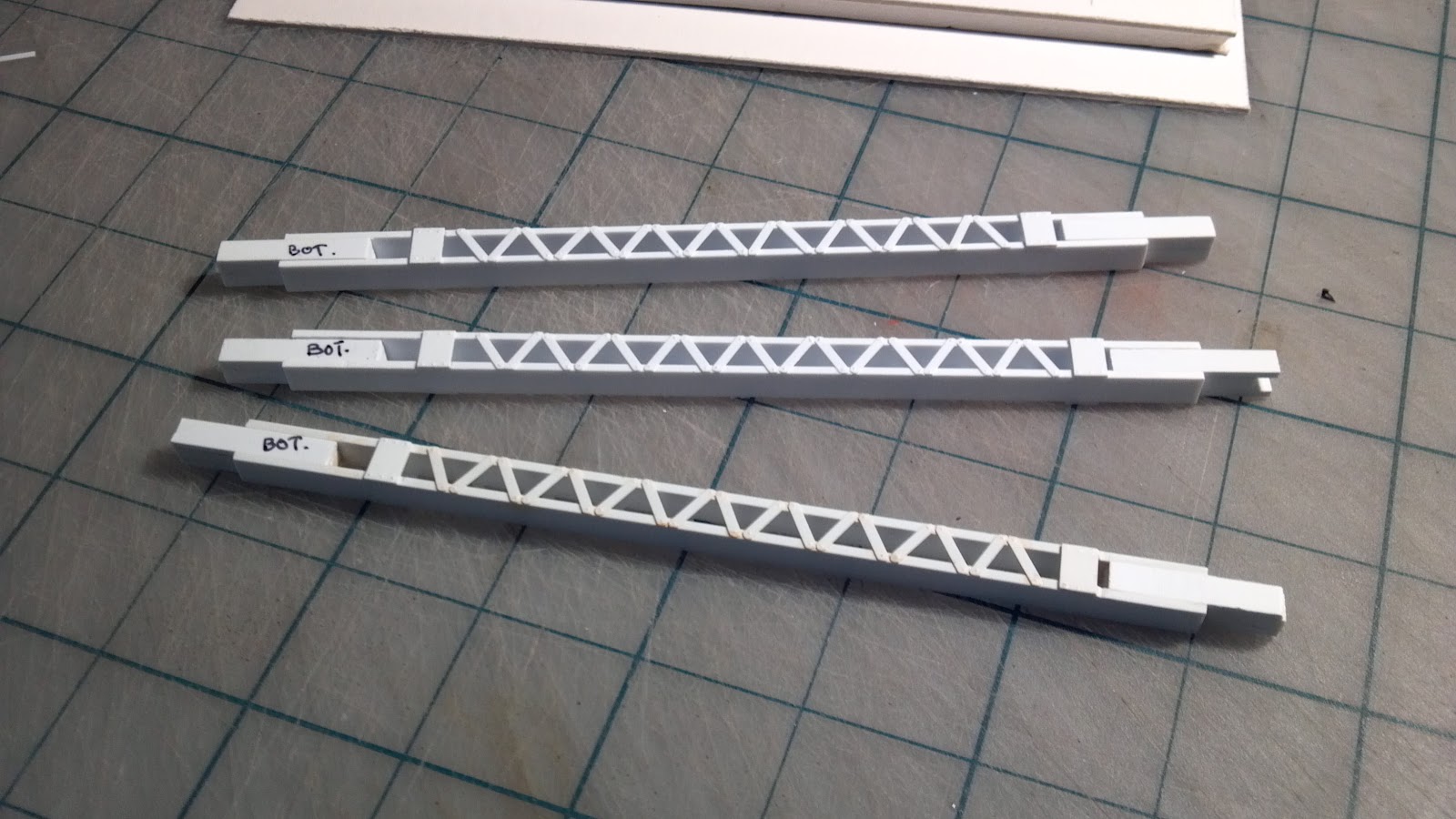
This is obviously one of the most difficult parts of the structure to build.  The girders shown form the uprights for each truss panel so six of these are required (3 for each truss) the remaining uprights have horizontal lacing which are much easier to fabricate.  It will take a while for me to build this span and I will probably even need a temporary structure across Seeley Creek.  I hope to have some updates on my progress posted here so that you can see how things are going.

Saturday, February 18, 2012

John Bortz's Pennsy Decapod

In 1956, most coal trains were powered by the 2-10-0 I-1sa locomotives with one on the point and two more about 100 cars back pushing on the rear. About three years ago I had the opportunity to acquire one of the I-1's scratch built by John Bortz. I know that there are at least two that he built in existence and I'm fortunate to own one of them. I'm not sure of the history of this particular unit, but I know that one of his I-1's won best in show at an NMRA convention in the 1980's. This engine is numbered 4618. It was built using a SSLS mechanism, but everything was scratch built using brass sheet and tube throughout. It weighs nearly 3-pounds and has a large can motor (back then SSLS drives all used Pittman open frame motors) and I must say that it's one of the finest running S scale steam engines that I've every owned - a real testament to John's skills. The video is from the shakedown run after I installed DCC with sound. The only modification that I made was doing the late-era Pennsy headlight generator/headlight swap. I wanted a late model I-1 so while I had the boiler disassembled, I did that modification. She's a real beauty! Anybody know where the other Bortz I-1's reside?

Thursday, February 16, 2012

Power for the People


I thought that I would take a moment and talk about some of the passenger train power found on the Elmira Branch, though in the era that I am modeling, there weren't many passenger trains on the line. But, there were dual purpose locomotives such as the FP-7 and the distinctive passenger GP-7s that roamed the Elmira Branch. FP-7's were relatively common on the Branch. The Pennsy owned 54 FP-7s (39 A-units and 15 B-units) and only a handful (four A-units and two B-units) were painted in the PRR's passenger scheme. Passenger service ended on the Elmira Branch in 1957 between Southport and Williamsport, PA. Since the period that I model is the Fall of 1956, some passenger service still existed and could logically have been handled by one of these dual service locomotives.


I chose to model FP-7 no. 9834 one of the four A-units in the Tuscan red scheme. No. 9834 was subsequently repainted into the Brunswick Green scheme, but beyond the era that I model. The model started out as an American Models FP-7 which I reworked extensively to recreate the Pennsy version. The first thing that I did was change out the motor for a reliable Sangami can motor, added DCC and Tsunami sound. Then I added the distinctive Pennsy water tank ahead of the fuel tank. Next came the antenna stanchions and wires, steam generator details, grabs above the windshield and cab door, and other roof top appurtenances. I built up a new flat front passenger style pilot from sheet styrene (the AM FP-7s only come equipped with the freight pilot), and added the front lift rings, nose grabs, and ladder rests on the side of the nose.


The rear of the AM shell left a lot to be desired in terms of detail. The rear end door was basically a flat un-detailed and molded on to the end of the car body. So, I built up a new door and door frame from styrene shapes so that it matched the quality of the exquisite F-unit offered by S-Helper Service. This was not as difficult to do as you might expect. I uses the SHS units as a guide and added the Pennsy lift rings to the top of the door frame. I painted the engine using Scalecoat's Tuscan Red and lettered the unit with Des Plaines Hobbies PRR 5-stripe decal set. Then I added some light weathering particularly on the unit's lower region to simulate dried mud and grime. Some black exhaust weathering was added to the roof near the fans and exhaust areas. when I was satisfied with the weathering, I added the stainless steel Farr air grills (also from Des Plaines Hobbies).


I now have some passenger power for the Elmira Branch that will look good on the head end and serve as a workhorse in freight service. Next time I'll feature the matching B-unit.


Wednesday, February 15, 2012

Progress Continues


Wow! I can't believe how long it's been since my last blog post. Though I haven't reported anything in the past 21 months, progress on the layout and the railroad room continues. Southport Yard is nearly complete from a track perspective. It's only nine tracks wide and a fraction of the prototype, but will still be an impressive yard in S-Scale. The yard is more than 24-ft. in length without the engine terminal. The view on the left is looking north from the south end of the yard. The engine terminal will be located at the far end of the yard in the corner of the room. The flextrack is by Tomalco, with all turnouts and crossovers hand built on wood ties. All tracks are wired for DCC.
This scene shows the north end of the yard. The turnout in the foreground is the same crossover shown in the video from my last post. The real challenge was to paint and weather the track so that the plastic flextrak matched the coloring and texture of the stained wood ties on the turnouts. Photos of Southport Yard, as well as most of the Elmira Branch itself, show the ballast being very dark most likely due to all the coal traffic and cinder ballast. I'm pleased with the track weathering and ballasting results. I will most likely complete the track detailing and weathering before installing the layout to the wall. It'll be much easier to work on the rear tracks while the layout is free standing.
Right now I am focusing on completing the railroad room itself. I recently read Brooks Stover's book on modeling the Buffalo Creek and Gauley Railroad in S-Scale (It's highly recommended and more info can be found here - http://www.buffalocreekandgauley.com/ ) and learned that you really need to finish the space before building the layout. No matter how anxious you are to build the layout of your dreams, it would be a mistake to try to work around a partially completed layout while trying to build the layout room. So, until I get more of the walls and room environment completed, updates on the layout itself will be somewhat limited. However, I have been busily working on locomotives and rolling stock for the branch and my upcoming posts will highlight progress in that area.